Reaction-wheel stabilization
 Independent controls
Hardware test platform
Feedback meets physical limits
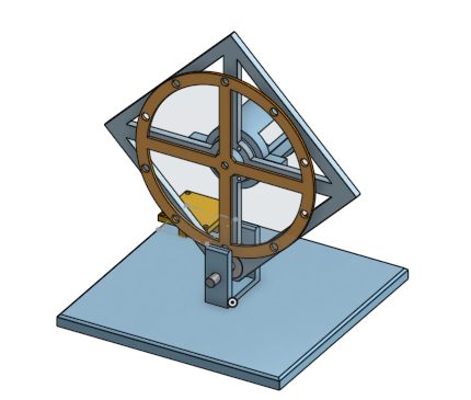
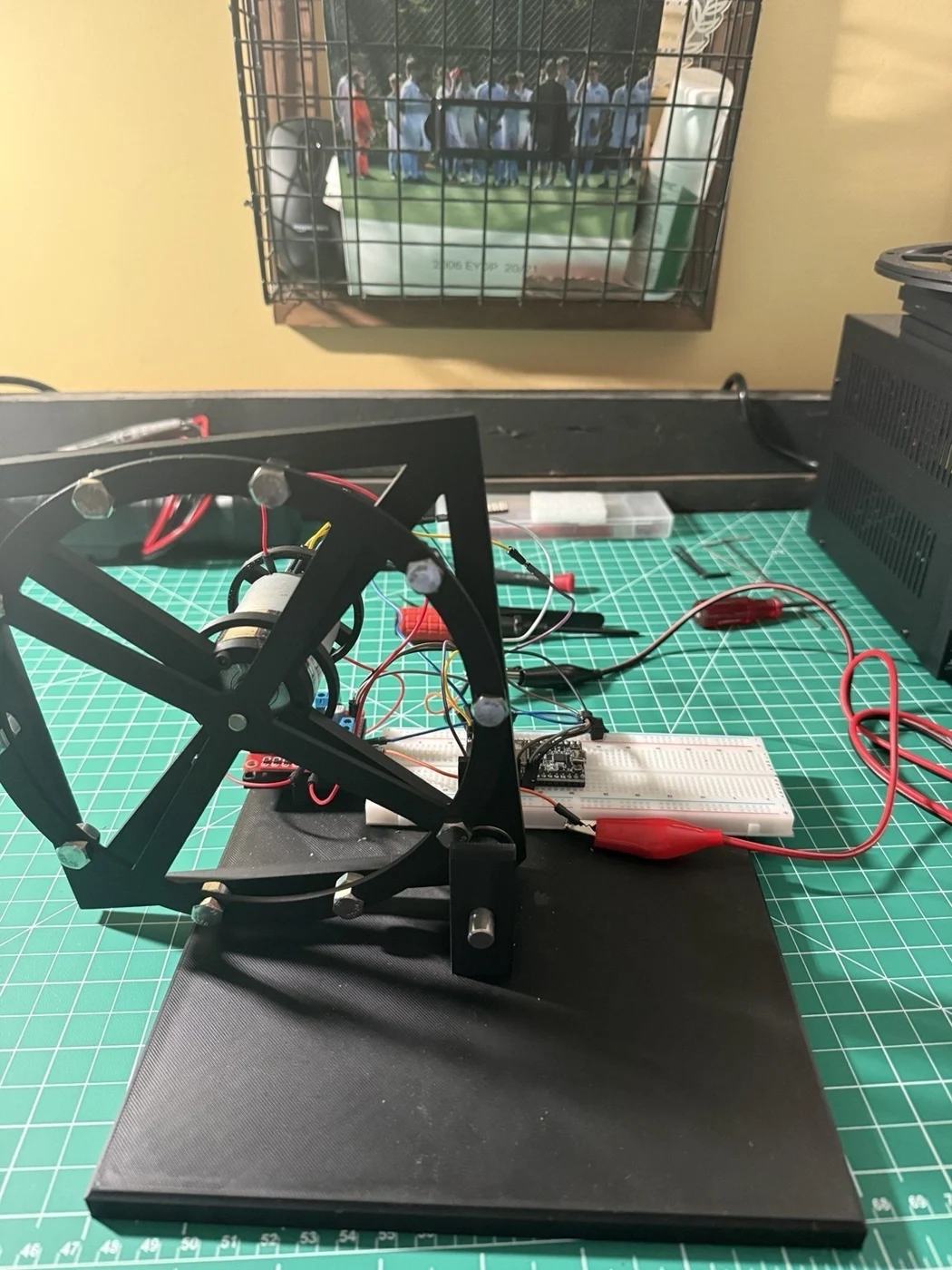
A one-degree-of-freedom balancing platform connecting inertia modeling, IMU-based state estimation, PID feedback, and iterative hardware tuning.
System architecture
- 01IMU angle / rate
- 02Kalman estimate
- 03PID controller
- 04Motor driver
- 05Reaction-wheel torque
Reaction wheel in operation
Hardware demonstration from the project repository, showing the wheel and balancing mechanism in motion.
Modeling & feedback
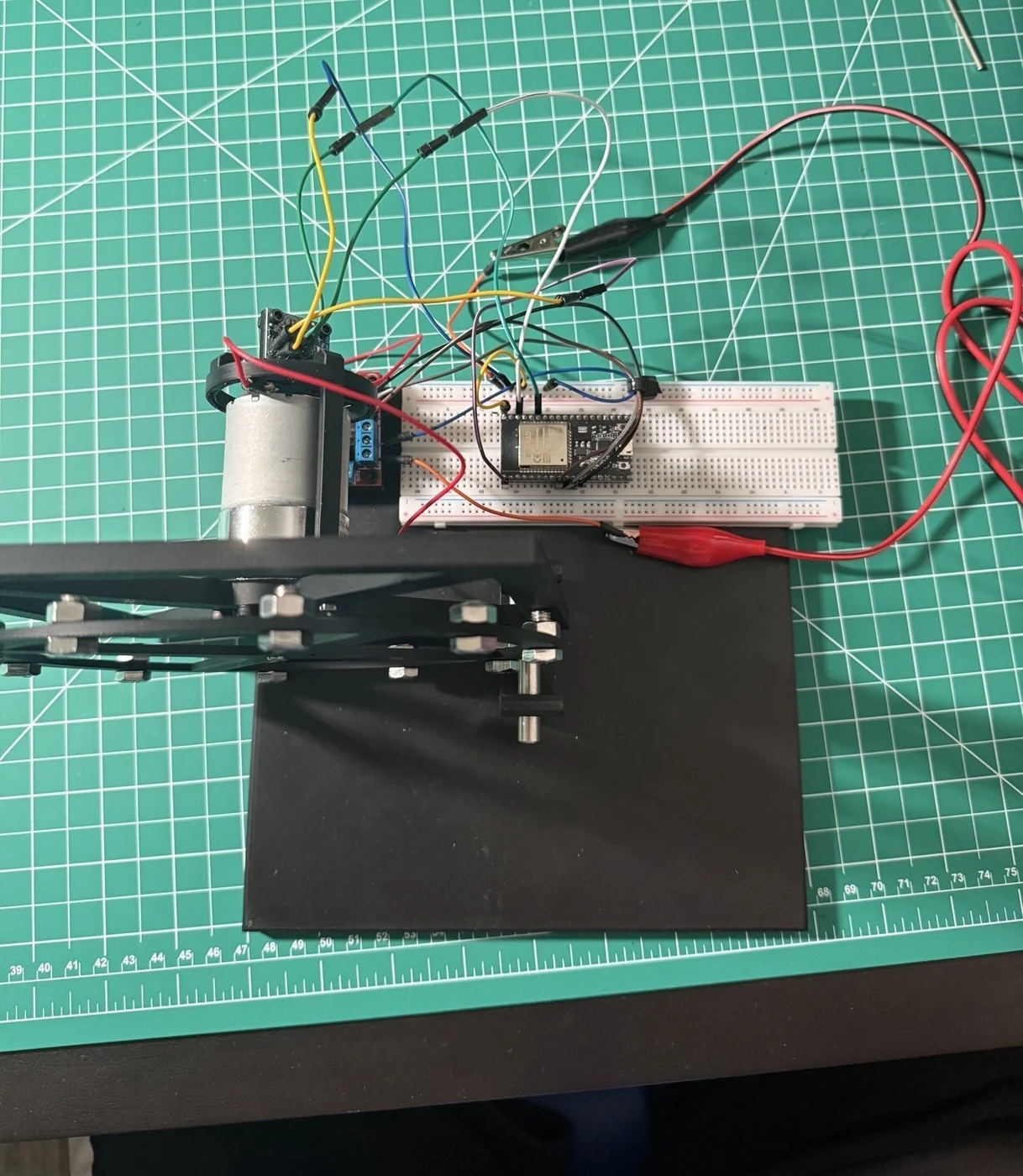
I modeled body and reaction-wheel inertia and implemented IMU-based PID feedback on an ESP32. The repository documents a 200 Hz fixed-period control loop, MPU6050 calibration and one-dimensional Kalman pitch estimation, and signed PWM output through an L298N driver.
Actuator behavior
Hardware iteration accounted for friction, motor deadband, minimum effective PWM, and saturation. Nonzero commands are raised to a minimum PWM magnitude of 90 to overcome stiction, which also makes small corrections coarse.
Observed limits
The repository reports correction from approximately 0.7 rad away from the target in constrained testing. This is a setup-specific observation, not a guaranteed recovery envelope. The 550 rpm motor reaches its usable wheel-speed range quickly, limiting further momentum exchange; torque calibration and driver losses remain modeling limitations.
Design & hardware